Digital Logic Sim (v0)
A downloadable game for Windows, macOS, and Linux
Please note: this is an old version of the program (version 0). If you're looking for the latest version, you can find it here.
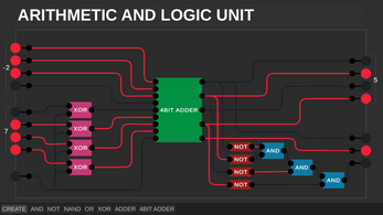
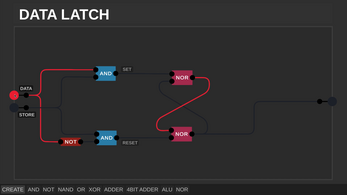
A minimalistic digital logic simulator. You start with an AND and a NOT gate, and from there you can build whatever you want.
I created this as a visualisation tool for my video series on the basics of how computers work, but have released it since a number of people were interested in trying it. May be buggy, and definitely lacking in many features! For something far more complete, take a look at alternatives like logisim.
Source code available here: https://github.com/SebLague/Digital-Logic-Sim/tree/Version-0
Latest build: v0.25 (6 December 2020)
| Status | Prototype |
| Platforms | Windows, macOS, Linux |
| Rating | Rated 4.6 out of 5 stars (120 total ratings) |
| Author | Sebastian Lague |
| Genre | Educational, Simulation |
Download
Click download now to get access to the following files:
Development log
- Version 0.25Dec 06, 2020


Comments
Log in with itch.io to leave a comment.
i like the look of this version more!
didnt work for me on mac ):
it does for me tho??
LEDS like the (in progress) 7/8 Segment Display.
You can connect them as outputs (anywhere on the screen u want) and you can select where they can be placed in the final chip layout so if you place the chip, you can see the leds from outside (like the display)
And maybe some extra labels
*Things that i would add
Here's what could make the simulation much better:
- Seeing inside chips
- Editing chips
- Delete Projects
- Saving incomplete chip designs
- Tabs so that you can switch between incomplete chip designs
- Zooming in and out
- Tri-state logic
- Read Only Memory (Nice for segmented displays)
- Inputs and outputs on the top and bottom of chips
- Ability to adjust the clock speed
- ASCII character display
Most of those features are coming, he needs a little more time i think. What he hasn't said anything about was ROM, tabs (i explained in my own comment that it would be hard when editing chips was implemented, but could still be useful), he hasn't said anything about clocks yet, i don't think that he will make an ASCII character display, but he will make a seven segment display. Using an encoder you could still use it as an ASCII display. If you're looking for a full display (i forgot how many pixels, but it was quite a lot. even with color. ) you can look for lime inc's refresh of the simulation, i don't think i can link them here. they have quite a few new toys :)
You can basically save unfinished chip designs and edit them later once he adds editing chips.
You can already rotate chips by pressing q and e while placing a chip.
I am quite excited about the other features you mentioned like zooming in and out (i asked for that myself too), ROM would be a REALLY REALLY nice addition for actually creating some programs, adjusting the clock speed, a ASCII character display, though we can make that ourselves and tri-state logic would also be cool.
Anyways, check out the lime inc remix if you can't stand the wait and check this page every day, he should soon release a update. (or check his youtube channel)
you can make a rom by using NOT gates for 1s and empty outputs for 0, if you want it to be 1 value permanently.
That is a possible way, however this gets very VERY tedious fast. I made a simple game for my virtual computer that required only 8 addresses of ROM (16 bits per address), which was doable, i'm currently planning on making a waay more powerful and advanced computer, so I can run more heavy workloads on it, but i would need multiple hundreds of bytes to make an actual game. At some point I will start using a 16x16 display for running the game, but for now this will do: my project.
You need to add ROMs
Looks cool
so there was a discord server for this stuff a while ago but i think maybe we should make a new one since its actually getting updated soon
A heads up. Someone called Lime Inc has stolen this program claiming its abandoned and "updated" it.
https://www.youtube.com/post/Ugkx9cCEsjQeW8cVD08DzEVDD4cYviCBNTRr
It was abandoned for two years.
And besides, they made some cool updates ;).
A clock, a seven-segment display, a full display and probably more that I forgot.
I'm happy the sim will be updated by Sebastian again though.
the last update was in 2020
WHERRRE CAN I FINNNNNNDDDDDD THEEEEEEE NEW UPDDAAATTTTEEEEEE??????????? PLLLLLEEEEAASSSEEE IIITTSS SOO GOOOOOOODDDD
In his latest video about this sim in the desc he wrote:
I've been completely rewriting the simulation program, and I still need to fix some bugs, add some UI etc. I'll add a link here soon when it's ready.
okay okay okay plesae fasstttttt :3
I've played this simulation for hours, and here are some features I want you to add.
First, I would like a Transparency feature to see inside chips. Second, I can't possibly get over the frustration of following your video to the last step and realizing that I messed up on the chip design for the previous chip so I have to start over again. So, I would like an Edit Chip feature that lets you select a chip then press EDIT and be able to edit the chip. Third, because of the previous issue, my projects tab is quite big. Therefore, I would like a Delete Project feature. That's about it! I hope to see the new version soon!
Hey Sebastian,
I played this simulation for hours, but there were some things you could maybe add in your next update.
Zooming in and out of the workspace would be really cool so we can make bigger and more complex chips. I know this is already possible by pressing ctrl&-, but the hitboxes don't match up which makes it basically useless.
I did see that you are creating a system for editing existing chips, Great with a capital G!
Being able to see the decimal count of a eight-bit number would be cool. Could be implemented like: When creating a new input/output you can choose between a normal in/out, a four-bit in/out, eight-bit and some custom number bits. Might need to make an option to enable/disable two's compliment though.
I think that by adding a edit button my next idea is less useful, i'll still mention it though: multiple tabs which you can work in. I don't know what to do about chips being inside other chips that are being worked on though, and like I said, this feature is not necessary.
I enjoyed your simulation a lot and wish you the best of luck with the new update, I know how stressful it can be to have announced a new update but still having to make a part of it, so take your time (but be quick if you know what I mean :P).
Hopefully he will make us able to zoom out on our area so we can do more complex things, such as 16 bit adders and the like.
i hope too
that would be w ngl
i want to make terrabyte storage in this
Couldn't you just create modules and string them together like he does in the video sires or would that be too complicated? I honestly just don't know.
you've never tried to make 64b ram before, haven't you
no
were's the chip library in his video?
not updated
Hes working on it. See: community posts
When will the windows version be updated?
Any chance there could be a chip sharing option. also how do you make things like LEDs and 8 segment displays? is there a way to delete chips that are made? i messed up at the beginning.
Sebastian didn't update DLS yet.
When will he update?
Lol, I don't know
most likely in a few days
apparently he's still working on the rewrite
Yah
ooh
C:\Users\[USERNAME]\AppData\LocalLow\Sebastian Lague\Digital Logic Sim\SaveData
This works for DLS 2, (you can delete the chip file) but I've no idea if it works for DLS original.
guys, how do i change the settings of the wires and make them have a little bit of delay ?
i don't think you can
sorry.
ps. I might be wrong
i wish we could. Maybe we could aslo change the color like he did.
I made synchronous counter mod 100. I figured out how to create a clock using only logic gates. Great tool for my university:)
How can I delete projects ? Or where they are save ? I cant find the projects to remove.I hope this question are not already exist.
Yes it does, and it is AppData\LocalLow\Sebastian Lague\Digital Logic Sim\SaveData\ on windows, generally unity game all follow the same logic
Created a Master-Slave Flip Flop and it does not work when created into a chip. Maybe because it need multiple tick to finish a clock cycle.
Can anyone help me with getting this I have tried for 2 days and I still don't know how to on windows 11
I use windows eleven, what do you need help with?
opening or downloading?
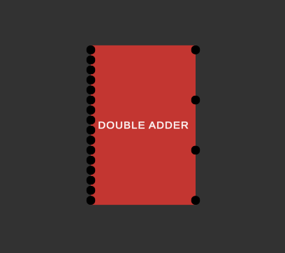
How do you make the decimal adder thing for the pins?
So...
(it takes 16 inputs, its insane)
Codes:
All 16 off = all off
1st input on = 2nd output on
2nd input on = 1st output on
3rd input on = 3rd output on
4th input on = 4th output on
5th input on = 1st output on
6th input on = 1st + 2nd output on
7th input on = 1st + 2nd output on
8th input on = 4th output on
finishing rest later
How Can I Get Your Block Into My Project?
you cant
to access the file containing the adder, you will need the file from their computer. To get a file from someones computer, they'll need to post the save file
oh . i see.
or you could ask them kindly to start a chrome remote access session and then connect to their computer and copy their file but they'd probably denied or you could ssh
This is a great project. Nice job!
Just one suggestion, there should be a way to go back and edit chips you’ve made in case you figure you messed up.
Also deleting/overwriting projects would be cool.
Cheers!
Another reason one might want to “edit” a chip is if you want to review the circuitry (in case you forgot or want to show someone).
A workaround I found for editing/deleting chips is going to AppData\LocalLow\Sebastian Lague\Digital Logic Sim\SaveData\ and removing the chip TXT files (or if you know how the app reads the data you can edit the file)
I use Linux (distro usually doesn’t matter) so that wasn’t great, but that gave me kind of a hint of where to look; thanks for the insight.
(For anyone else using Linux look in
~/.config/unity3d/Sebastian Lague/Digital Logic Sim/Save Data/SCTK/.)This is a good workaround. Thank you for the idea.
Better facilities for managing chips would be great when you have lots of them. - Making a new one with the same as an old one should ask you if you’d like to overwrite the old one instead of doing nothing.
I very much agree
I'm pretty sure it'll be in the new update. Because in his new video an edit button was shown, and there seems to be a load of new features
What video?
https://www.zamzar.com/download.php?uid=4e29e414975f58dc9f74f8af5ae6556-316359da... 2 bit mem
2https://www.zamzar.com/download.php?uid=728a919d599846fe3adaa6b32de24ef-75be548b... 1 bit addresser
How to delete chips? also good job!
click on it then press the delete button on your keyboard
not backspace
To delete chips on Windows:
press "win + r" and type "appdata" into the textbox then click "run".
Look for the folder called "Sebastian Lague" and open it, then open the folder "Digital Logic Sim". Click on "saveData" and look for the chip. Right click on the .txt file and press "show more options", press delete then reload DLS
the chip will no longer exist
First make a NAND gate by putting a NOT gate in an AND gate’s output. Then connect 2 NOT gates’ output to the NAND gate’s inputs and voilà, you have an OR gate!
Wait.. PURE Code? Like Only Ands And Nots?
How to reset the bord without quitting the project?
just delete all the chips on the board with the DELETE button, not the BACKSPACE button
what about wires?
In the video sometimes he says thats not how he would do it so he would deletes wires
hold down left click and drag across screen, then press backspace or delete, it should delete the wires and all the chips
how do I create a chip?
add chip in board, make input and output, on top of screen enter name of chip, click create, done
to make input press +, to delete input press -
how do i get the numbers on the inputs and outputs
It's a group of inputs. Just press + to add one and - to remove 1
how do you add inputs to custom chips
+
is it just me or is there no way to save a project, (in version 1 or 2) usually when i reload a project everything is missing and if the chips are there, then the circuits connecting them have all disappeared. and in version 2 where you can edit the chips, the circuits are all missing.
projects autosave, unchipped circuits dont (circuits that havent been assigned to a chip)
how
4 toggleable 4 bit register
Hi I was wondering if the output lines from a smart microwave <span class="NormalTextRun SCXW259443053 BCX0" <the="" output="" lines="" from="" a="" smart="" microwave="" <="" span="">is</span> formed from all possible products of its three input variables and its complements. made any sense to you. If so how would you do this? Because I am still relatively new to the scene and i am not sure what to do at the ouput. Any help is greatly appreciated! <3
Edit:
idk why it says the "span class"
im a logic master luckily
DLS2 : https://banderacat.itch.io/digital-logic-sim2
the game is very cool but there are alot of basic features missing such as deleting made chips and projects or editing them which makes it hell if you forgot a wire in a chip and now doesnt work and its stuck there
by "deleting chips" i meant deleting them on the toolbar so that they dont exist anymore and dont take up space on the toolbar
theres an edit chip option in V2